As a consultant working in the field of systems thinking, I am continually amazed by the ease with which people are able to read and draw causal loop diagrams (CLDs) with just a little instruction and coaching. On the other hand, I am continually frustrated by the fact that many of these same people can read stock and flow diagrams with little difficulty, but find creating these maps themselves a much greater challenge.
I strongly believe that stock and flow diagrams offer a deeper understanding of a system than do causal loop diagrams. Nevertheless, in the past, I found it difficult to get more than a small handful of clients to develop the facility to build them. Despite its obvious benefits, the rigor of the stock and flow language comes at a price—it is more difficult to learn. While companies that create simulation software have made enormous advances in their products, vastly simplifying the model-building process, we still have a long way to go in learning how to help people develop the facility to create even simple models.
High Performance Systems, the creators of the ithink® software, have stuck firmly to their belief that a true understanding of the dynamics of any system requires an appreciation of the underlying stock and flow structure. For that reason, their software does not provide the facility to build CLDs. The best they offer are “Loop Pads,” which they describe as “. . . simple pictures that identify the cause and effect processes that work to generate dynamic behavior patterns.” To display these pictures, you have to build the stock and flow model first.
The challenge is to find more effective ways of helping clients develop an understanding of the structural dynamics of the system they are studying, while acknowledging that they usually find CLDs an easier place to start than stock and flow diagrams. To that end, I have developed an approach to model building that uses ithink in a slightly unorthodox way to start clients at a relatively easy place and move them quickly to a more sophisticated understanding of a given system using stocks and flows. Paradoxically, this technique capitalizes on the software’s unwillingness to let users draw CLDs.
From Feedback Loops . . .
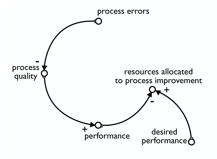 To follow this process, you must use version 6.0 of the ithink software, which allows you to minimize the size of the converter icon. Start by changing the defaults to set the converters to small. Doing so lets you use the converters as you would the variables in a CLD. Then use the text box facility, which is one of the objects on the menu bar, to create the polarity signs (, “+” or “-,” which correspond to “s” and “o”). For example:
So far so good. Up to this point, we are simply building a CLD in which “resources allocated to process improvement” are influenced by current “performance” and “desired performance.” However, when we try to create a causal link between “resources allocated to process improvement” and “process errors,” an error message appears indicating that such an action would create a circular connection.
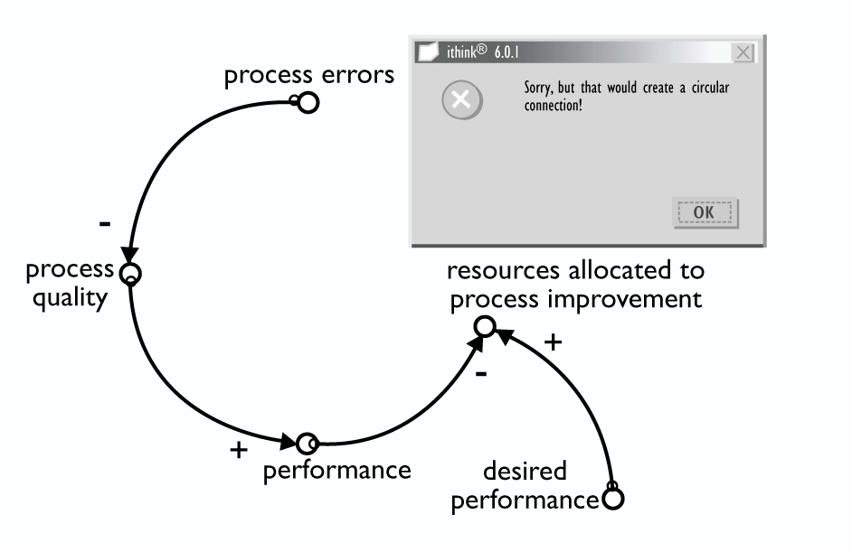
The nature of the mathematics that underlies the stock and flow language means that the software is unable to calculate the value of any converter or flow when they loop back on themselves. As the help files state: “In drawing connector linkages, you may encounter an alert which tells you that circular connections are not allowed. Mechanically, this alert means that you have attempted to create a chain of converters or flows, such that one converter or flow ultimately depends upon itself. The software cannot resolve the resultant simultaneous equations.”
. . . to Stocks and Flows
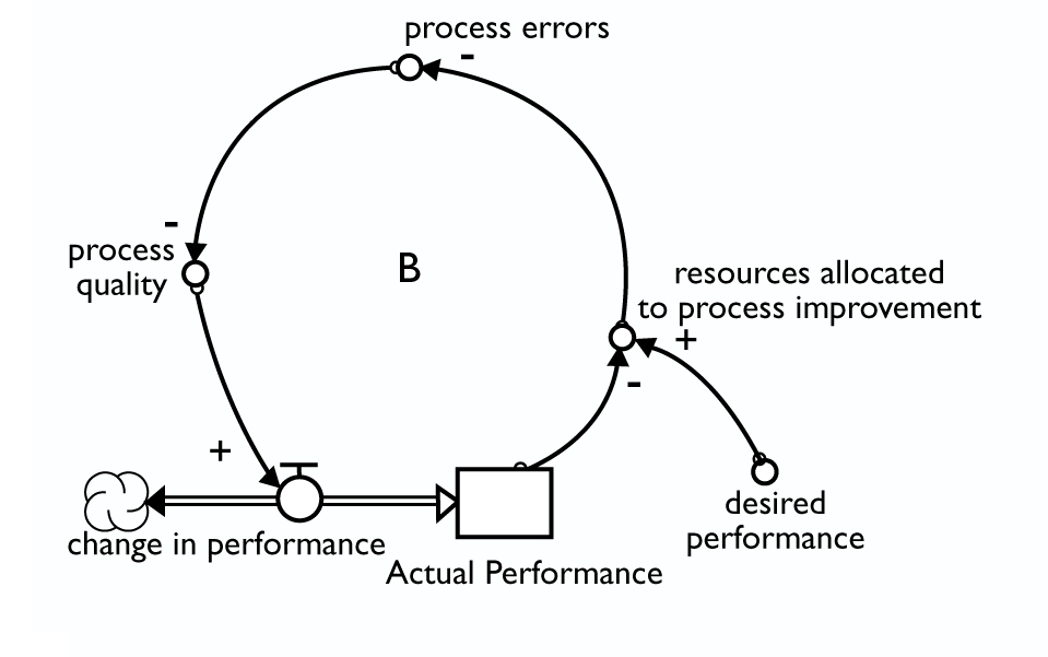
To get past this barrier, we must create at least one stock somewhere in the loop. This process forces us to look more closely at the structure of the loop we are creating and identify one or more stocks. Every feedback loop has an accumulation—it is this accumulation that generates the feedback dynamics. In this example, the issue for the team was how actual performance levels drove “resource allocation to process improvement.” With this in mind, we can now make a simple modification to the CLD by converting the variable “performance” into a stock.
We are now a step closer to gaining a deeper understanding of the feedback processes involved in this structure. We have done so, however, by beginning with a process that clients are familiar and comfortable with and then moving to a structural understanding through one simple step. How we develop the model from this point forward depends on your goals. We could stay with this loop and simply develop the stock and flow structure for each variable.
Going into Greater Detail
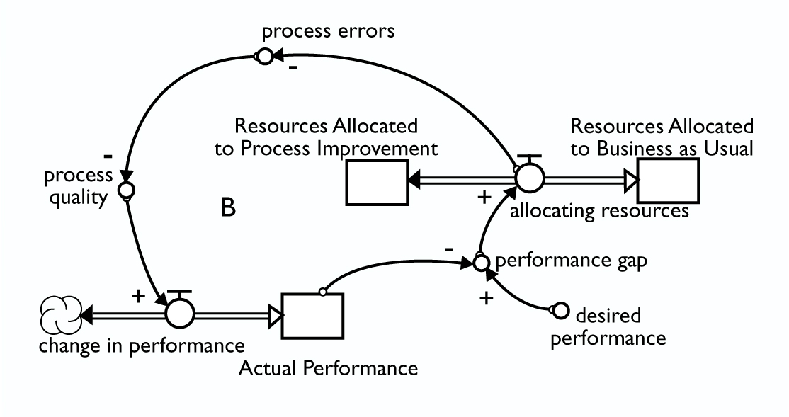
We also might want to explore a certain part of the structure in greater detail. For example, we might be interested in the dynamics involved in a process-improvement program. In this case, the team realized that the resource allocation decisions were not only determined by actual performance but by the gap between actual and desired performance:
On the other hand, we may want to develop a loop to explore the impact of process quality. One possibility could be:
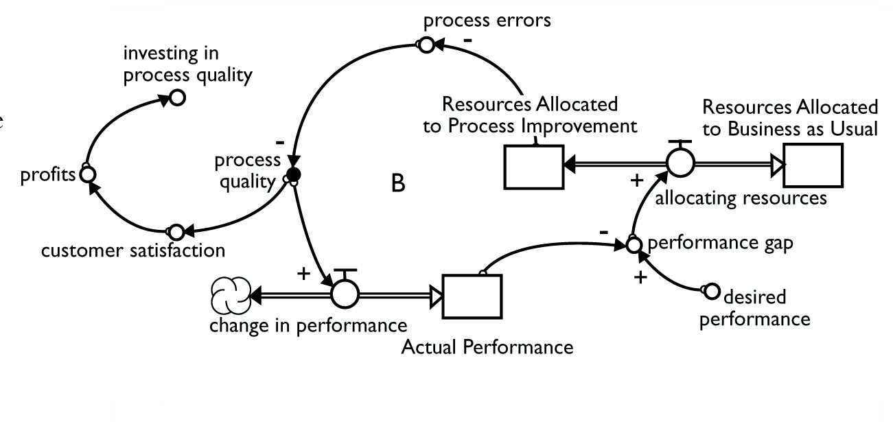
Once again, when we try to close the loop by connecting “investing in process quality” with “process quality,” we will receive an error message that circular connections are not allowed. How we respond to this message depends on what we are trying to understand with the model. If we want to examine the financial implications in more detail, we could begin to unravel the structure underlying the variable called “profits.” For example:
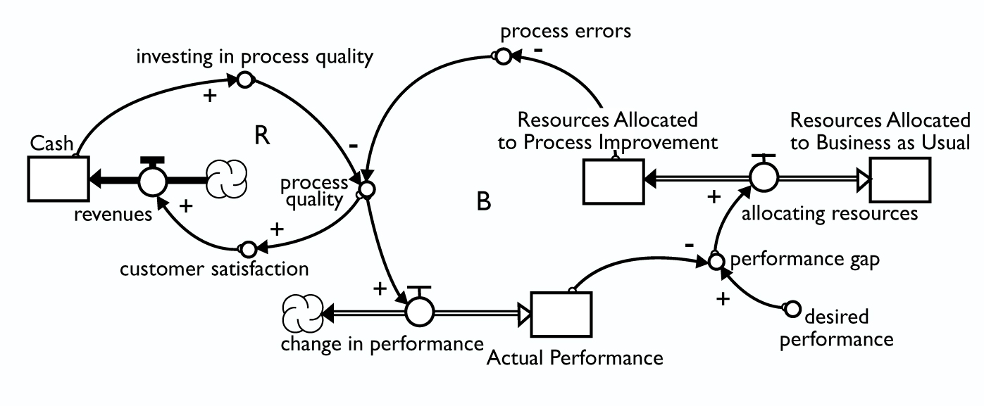
The key point is that we always anchor the model development process in something the client is familiar and comfortable with—the development of CLDs. We then force the software to highlight a logical error to provide a stepping stone to unfolding the stock and flow structure. I have found that, using this technique, more clients are able to develop an ability to create their own stock and flow models than before. Prior to using this approach, I found that clients viewed CLDs and stock and flow diagrams as separate and distinct languages. Since I’ve implemented this process, I have noticed that they have begun to see the similarities, rather than the differences, between the two. As a result people are less mystified when working with stocks and flows, seeing them embedded in the feedback loops of CLDs.
David Rees is the director of High Performance Learning Systems, a consultancy firm specializing in applying systems thinking principles and tools in public and private sector organizations. He is also a research fellow at the Centre for the Design of Innovative Systems at UNITEC in Auckland, New Zealand.